Vertical Speed Indicator
The Vertical Speed Indicator (VSI) is an instrument that displays the rate of climb and descent to the pilot.
Introduction to Vertical Speed Indicator
- The Vertical Speed Indicator (VSI) is an instrument that displays the rate of climb and descent to the pilot by measuring rate-of-pressure changes.
- Pressure changes provide vertical speed indications for the pilot to determine the aircraft's trend before the altimeter registers changes.
- While not required to function or be calibrated for flight, the vertical speed indicator does contain inherent errors for pilots to consider as part of their preflight actions.
- Newer aircraft utilize modern Inertial Reference Unit (IRU), Inertial Navigation System (INS), and Attitude Heading Reference System (AHRS) systems for glass displays.
- As with any system or instrument, anomalies and malfunctions are possible, requiring detailed knowledge of the indicator and related systems.
Vertical Speed Indicator Key Highlights
- The vertical speed indicator (VSI) displays the rate at which an aircraft is climbing or descending.
- The VSI measures changes in static air pressure to calculate vertical speed in feet per minute.
- Positive indications show climbs, while negative indications show descents relative to the aircraft’s current altitude trend.
- The instrument contains a calibrated leak that allows pressure changes to be measured over time.
- Vertical speed indicators help pilots establish and maintain precise climb and descent rates during flight operations.
- The VSI is especially useful during instrument flight, altitude changes, and stabilized approach procedures.
- Traditional VSIs have a slight lag in response because they rely on gradual pressure equalization.
- Instantaneous vertical speed indicators (IVSIs) reduce lag and provide faster vertical trend information.
- Pilots should cross-check VSI indications with the altimeter, attitude indicator, and airspeed indicator during altitude changes.
- Understanding vertical speed indicator operation improves altitude control, instrument proficiency, and overall flight safety.
Pitot-Static System
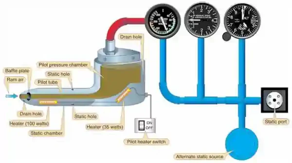
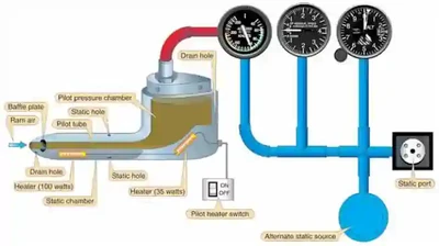
- Pitot Static systems measure and compare air pressures from the Pitot tube and static port
- These measurements display indications for the Airspeed Indicator (ASI), Altimeter, and Vertical Speed Indicators (VSI).
- The system consists of two components:
-
Pitot Tube:
- Invented by Henri Pitot in 1732, the Pitot tube measures fluid flow (air) velocity.
- The device measures ram (forced) air through a small hole in its front.
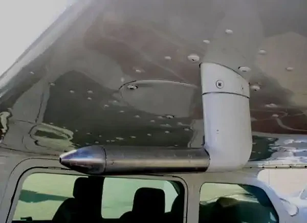
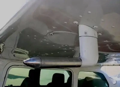
- The device's placement is often on the front of the aircraft or an airfoil to capture smooth (undisturbed) air. []
- The ram air captured produces an airspeed reading on the airspeed indicator (ASI).
-
Pitot Heat:
- Pitot Tubes are often electrically heated, which can prevent and remove ice accumulation. []
- Note that these devices should only be utilized during ground operations when necessary.
- Leaving them on unnecessarily can cause heat to the point of damage/malfunction.
- When airborne, the airflow otherwise cools the device.
-
Static Port:
- Static ports measure ambient still-air atmospheric pressure.
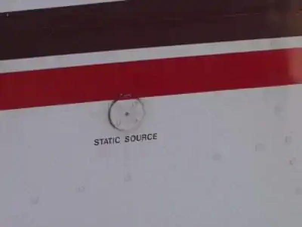
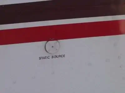
- Typically, ports are flush mounted on the side of the aircraft where air is undisturbed. []
- Some aircraft may utilize heated static ports to mitigate ice.
- Dual ports remove errors due to slips and skids.
- Responsible for Airspeed Indicator, Altimeter, and Vertical Speed Indicators.
- The POH/AFM contains any corrections to the airspeed for the various flaps and landing gear configurations.
-
Alternate Static Source:
- An alternate static air source valve is available for emergencies on some aircraft.
- If the alternate source ports inside the airplane, where static pressure is usually lower than outside, selection may result in the following erroneous instrument indications:
- The altimeter reads higher than normal.
- Indicated airspeed (IAS) reads greater than normal.
- VSI momentarily shows a climb.
- Many POHs provide a correction table and aircraft-specific instructions.
- The alternate static source is not corrected for non-standard pressure (as with an altimeter's Kollsman window).
- Using alternate static sources may impact other instruments that rely on static pressure (i.e., autopilots, TCAS, transponder, etc.).
- Using alternate static sources can also decrease the accuracy beyond the 75 feet recommendation outlined in the Aeronautical Information Manual.
Vertical Speed Indicator Design and Function
- Vertical Speed Indicator (VSIs) measure rate-of-pressure change to provide a rate of climb or descent indication. []
- Air is provided through the static ports where it enters a diaphragm (aneroid).
- The diaphragm expands/retracts to indicate a climb/descent by measuring the ambient changes in pressure within the static system.
- As pressure drops, the aneroid compresses, indicating a climb
- As the pressure increases, the aneroid expands, indicating a descent
- Through a calibrated leak/orifice, the air leaves the instrument case slower than the aneroid and allows for a stabilized indication of pressure change on the face of the instrument.
- As the aircraft levels off, pressure no longer changes and the pointer returns to its zero position
Vertical Speed Indications
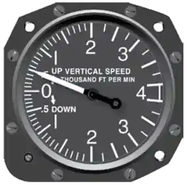
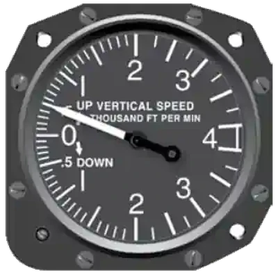
- Vertical speed indicator start with a "0" indication at the 90 degree position and have notches to indicate the rate of climb both up and down that circle the dial
- Indicators may be calibrated differently depending on the country and its specified indication, which can be:
- Feet Per Minute (FPM)
- Meters Per Second (MPS)
- Nautical Miles Per Hour (Knots)
Vertical Speed Indicator Regulations
- There are no regulations that require a vertical speed indicator by federal aviation regulations.
- The vertical speed indicator is not required to meet a calibration standard or even be functional for flight to be legal.
- Always check the Pilot Operating Handbook to learn the specifics of it's operation.
Instrument Errors
- The vertical speed indicator inherently lags, but is more sensitive than an altimeter.
- This lag can result in a 6-9 second lag to stabilize which will inhibit accurate readings during turbulence or abrupt control movements.
- Instantaneous VSIs (IVSIs) use two accelerometer actuated pumps to give you a lag free indication
- Alternate sources of static, when selected, will typically show a momentary climb.
- This is due to pressure differences in the cockpit than outside.
- A blocked static port will give a zero indication.
Vertical Speed Indicator Preflight Actions
- If it indicates anything other than a zero feet per minute climb or descent on the ground, then the instrument can still be used, but that indication is the new "zero."
- This, of course, is highly discouraged if the error is such that a mistake could create a serious hazard to flight, especially in weather.
Vertical Speed Indicator Anomalies and Malfunctions
- Pitot-Static system errors are generally the highest at low airspeed (high angles of attack)
-
Static Port Blockage:
- If in a real emergency, malfunctions can be corrected with alternate air or breaking the glass on a Pitot static instrument (VSI).
- The trapped pressure in the static system causes the altimeter to remain at the altitude where the blockage occurred.
- The VSI remains at zero.
Vertical Speed Indicator Interactive Scenario
Interactive Scenario
Loading scenario details...
Decision 1
0%
Scenario Complete
Private Pilot (Airplane) Operation of Aircraft Systems Airman Certification Standards
Private Pilot (Airplane) Operation of Aircraft Systems Airman Certification Standards
- Objective: To determine whether the applicant exhibits satisfactory knowledge, risk management, and skills associated with safe operation of systems on the airplane provided for the flight test.
- References: FAA-H-8083-2 (Risk Management Handbook), FAA-H-8083-3 (Airplane Flying Handbook), FAA-H-8083-23 (Seaplane, Skiplane, and Float/Ski Equipped Helicopter Operations Handbook), FAA-H-8083-25 (Pilot Handbook of Aeronautical Knowledge); POH/AFM.
- Note: If K1 is selected, the evaluator must assess the applicant's knowledge of at least three sub-elements
- Private Pilot Operation of Aircraft Systems Lesson Plan.
Knowledge 2 ACS Elements
-
PA.I.G.K1: Airplane systems, including:-
PA.I.G.K1a: Primary flight controls. -
PA.I.G.K1a: Secondary flight controls. -
PA.I.G.K1c: Powerplant and propeller. -
PA.I.G.K1d: Landing gear. -
PA.I.G.K1e: Fuel, oil, and hydraulic. -
PA.I.G.K1f: Electrical. -
PA.I.G.K1g: Avionics. -
PA.I.G.K1h: Pitot-static, vacuum/pressure, and associated flight instruments. -
PA.I.G.K1i: Environmental. -
PA.I.G.K1j: Deicing and anti-icing. -
PA.I.G.K1k: Water Rudders (ASES, AMES). -
PA.I.G.K1l: Oxygen Systems.
-
-
PA.I.G.K2:
Risk Management 3 ACS Elements
-
PA.I.G.R1: -
PA.I.G.R2: Management of a system failure. -
PA.I.G.R3: Monitoring and management of automated systems.
Skills 2 ACS Elements
-
PA.I.G.S1: Operate at least three of the systems listed in K1a through K1l appropriately. -
PA.I.G.S2: Complete the appropriate checklist(s).
Private Pilot (Airplane) Systems and Equipment Malfunctions Airman Certification Standards
- Objective: To determine whether the applicant exhibits satisfactory knowledge, risk management, and skills associated with system and equipment malfunctions appropriate to the airplane provided for the practical test
- References: FAA-H-8083-2 (Risk Management Handbook), FAA-H-8083-3 (Airplane Flying Handbook), FAA-H-8083-25 (Pilot Handbook of Aeronautical Knowledge); POH/AFM.
- Private Pilot (Airplane) Systems and Equipment Malfunctions Lesson Plan.
Knowledge 15 ACS Elements
-
PA.IX.C.K1: Causes of partial or complete power loss related to the specific type of powerplant(s). -
PA.IX.C.K1a: [Archived]. -
PA.IX.C.K1b: [Archived]. -
PA.IX.C.K1c: [Archived]. -
PA.IX.C.K1d: [Archived].
-
-
PA.IX.C.K2: System and equipment malfunctions specific to the aircraft, including: -
PA.IX.C.K2a: -
PA.IX.C.K2b: -
PA.IX.C.K2c: -
PA.IX.C.K2d: Electronic flight deck display malfunction. -
PA.IX.C.K2e: -
PA.IX.C.K2f: Inoperative trim.
-
-
PA.IX.C.K3: Causes and remedies for smoke or fire onboard the aircraft. -
PA.IX.C.K4: Any other system specific to the airplane (e.g., supplemental oxygen, deicing). -
PA.IX.C.K5: Inadvertent door or window opening.
Risk Management 4 ACS Elements
-
PA.IX.C.R1: Checklist usage for a system or equipment malfunction. -
PA.IX.C.R2: -
PA.IX.C.R3: Undesired aircraft state. -
PA.IX.C.R4: Startle response.
Skills 2 ACS Elements
-
PA.IX.C.S1: Describe appropriate action for simulated emergencies specified by the evaluator, from at least three of the elements or sub-elements listed in K1 through K5 above. -
PA.IX.C.S2: Complete the appropriate checklist(s).
Common Training Aircraft Pitot-Static System Characteristics
-
Piper Arrow:
- Composed of a heated Pitot tube on the lower left wing
- Two static ports are located on each side of the fuselage
- Alternate static air (below the pilot control yoke) provides static pressure from inside the cabin
-
Cessna 172:
- Composed of a heated Pitot tube on the lower surface of the left wing
- An external static port is located on the lower left side of the forward fuselage
- Pitot Tube consists of a heating element, a 5-amp switch/breaker, and associated wiring
- Alternate static (below throttle) provides pressure from inside the cabin
Vertical Speed Indicator Knowledge Check
Private Pilot

Core Knowledge Review
Review the foundational knowledge, key concepts, and practical considerations for Vertical Speed Indicator.
Foundational
Immediate Feedback
Answer Explanations
Commercial Pilot

Advanced Application
Apply your knowledge of Vertical Speed Indicator to advanced operational scenarios, risk management, and aeronautical decision-making.
Advanced
Scenario Based
Risk Management
Why Take a Quiz?
Quizzes reinforce key concepts, identify knowledge gaps, and build confidence for real-world decisions in the cockpit.
Vertical Speed Indicator Conclusion
- The vertical speed indicator can go by many different names to include:
- Variometer
- Rate of Climb Indicator
- Vertical Velocity Indicator
- Vertical Speed Indicator (VSI) is however, most common
- Always keep in mind the effects of parallax error.
- Still looking for something? Continue searching:
Vertical Speed Indicator References
- Federal Aviation Administration - Pilot/Controller Glossary.
- Aeronautical Information Manual (1-1-15) Inertial Reference Unit (IRU), Inertial Navigation System (INS), and Attitude Heading Reference System (AHRS).
- CFI Notebook.net - Pilot Information Handbook.
- CFI Notebook.net - Pitot Static System.
- Instrument Flying Handbook (3-8) Vertical Speed Indicator (VSI).